8 694 läst · 30 svar
9k läst
30 svar
Rumsbetjäningssystem - vad heter det?
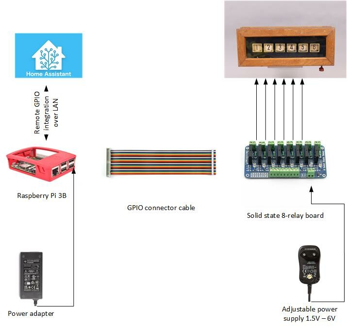
Jag lyckades få tag i en duktig elektriker som installerade en Fallklafftablå som jag köpt på tradera. Naturligtvis hade det funnits en tidigare. Men nu funkar den! Han föreslog trådlöst men jag ville använda ledningarna som fanns.
M Messier1994 skrev:
Oftast tror jag man fick en kopp kaffe när man tryckte på knappen.C ChristinaHallbergsstugq skrev:
") Tyvärr har nog få kvar tjänstefolket, så när man trycker på knappen händer nog inte så mycket mer än att ett nummer trillar ned. Om man inte har en snäll man/fru...
Tyvärr har nog få kvar tjänstefolket, så när man trycker på knappen händer nog inte så mycket mer än att ett nummer trillar ned. Om man inte har en snäll man/fru...Känns lite hönan och ägget, när du tryckte på knappen så kom elektrikern och kopplade in den fast den ännu inte var inkopplad, men smidigt med en elektriker i tjänste-staben.
Sorry för skämtet. Ja, en elektriker kan nog koppla in detta, det är väldigt enkel teknik. Det svåra är att dra och "gömma" kablarna, om de tagits bort vid renovering. Finns alla kablar och knappar kvar är det inte lång tid som behövs för att koppla in det igen.
Jag behöver nu gå tag i en knapp till golvet i matsalen. Kontakten finns kvar.

Är det en "vanlig" sådan med sladd du är ute efter?C ChristinaHallbergsstugq skrev:
Ligger en ute på Tradera nu:
https://www.tradera.com/item/343334/670130452/hang-strombrytare-i-bakelit-
Ser de komma ut lite då och då - vanligare än själva tablåerna iallafall.
Nej, en knapp att fästa i parketten.
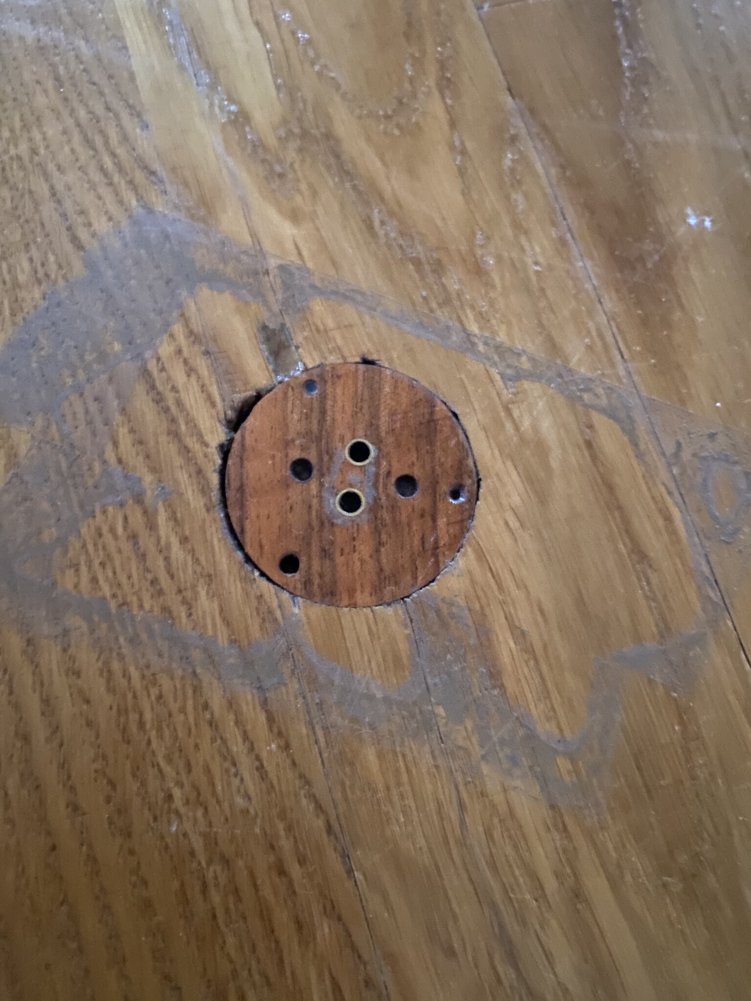
Jag vill egentligen ha en originalknapp
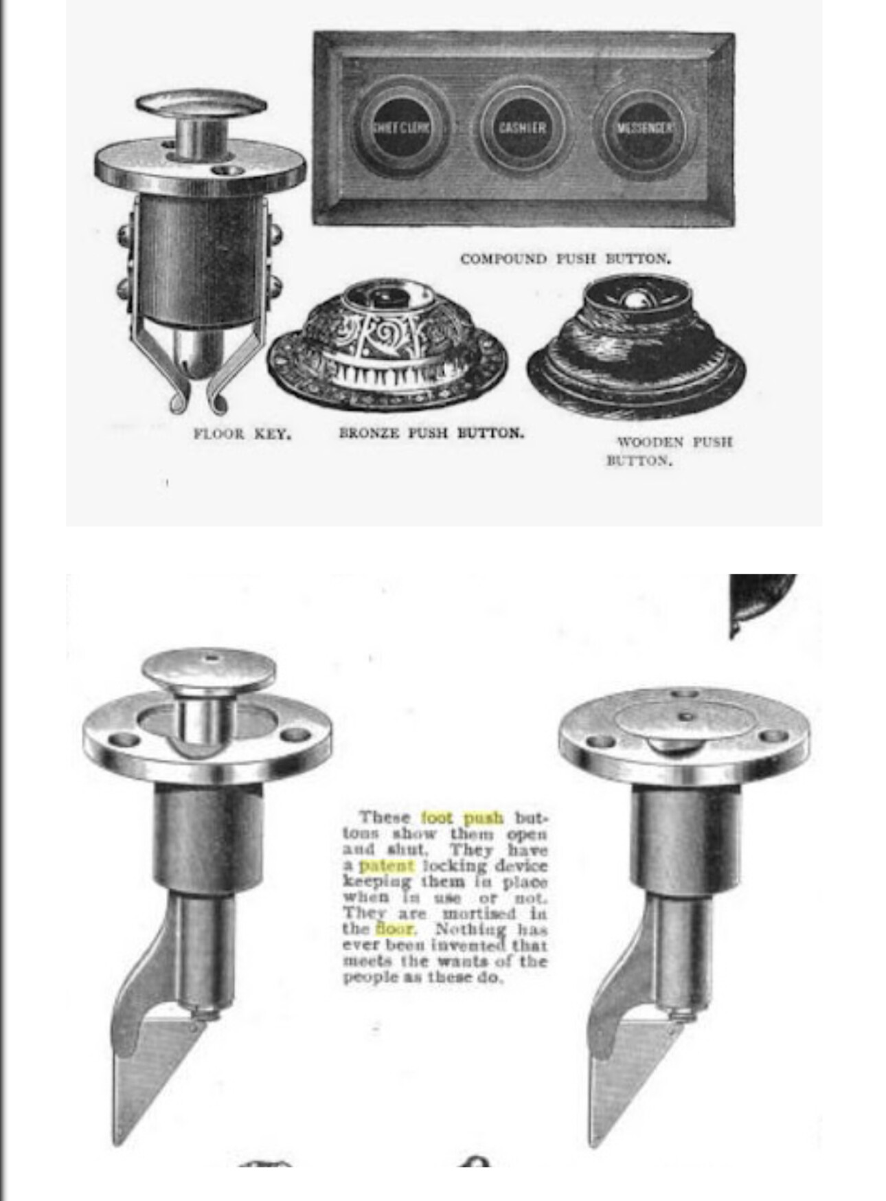
Är väl så här de ska se ut:C ChristinaHallbergsstugq skrev:
Inloggade ser högupplösta bilder
Logga in
Skapa konto
Gratis och tar endast 30 sekunder
Inloggade ser högupplösta bilder
Logga in
Skapa konto
Gratis och tar endast 30 sekunder
Gissar att de kan vara svåra att finns i Sverige. Skulle söka på EBay i England och USA.
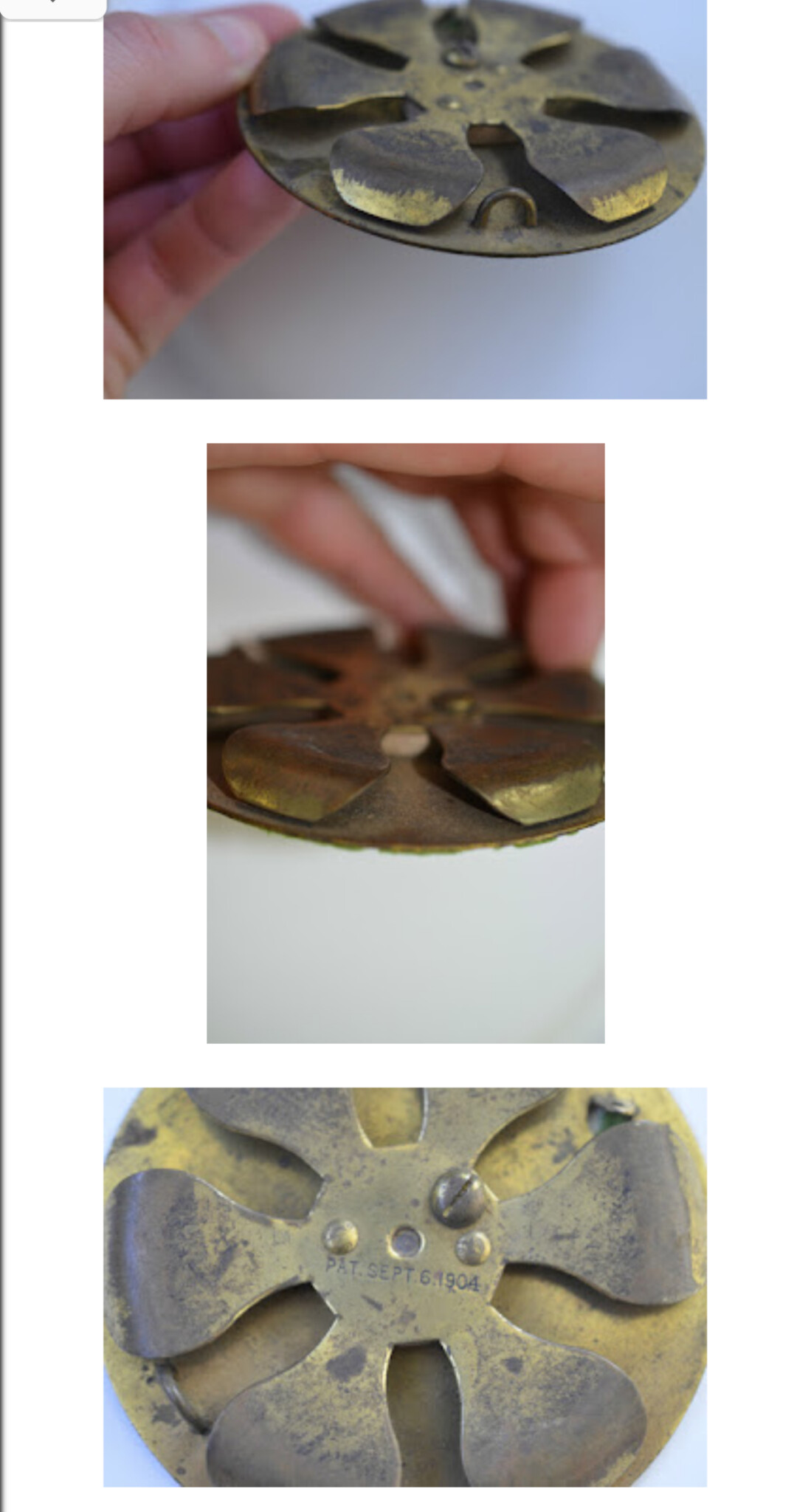
En sån här måste ju gå att göra själv:

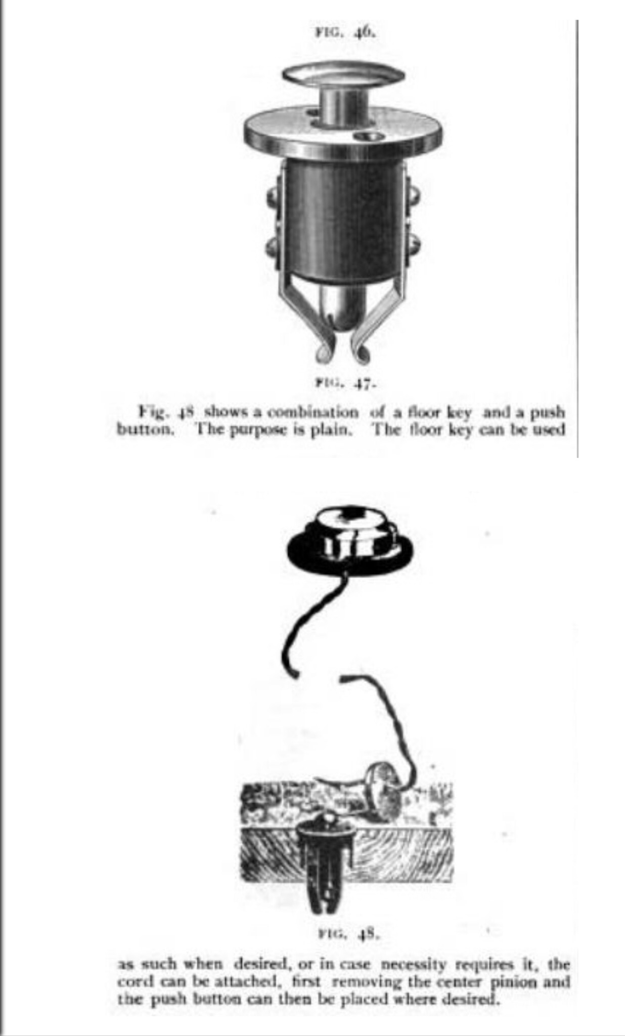
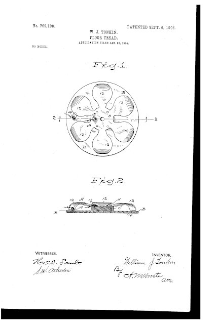
Patentansökan från 1904:
Inloggade ser högupplösta bilder
Logga in
Skapa konto
Gratis och tar endast 30 sekunder
Patentansökan från 1904:
UNITED STATES Patented September 6, 1904.
PATENT OFFICE.
WILLIAM J. TONKIN,
ANSON IA ELECTRICAL COMPA CORPORATION OF CONNECTICUT.
FLOOR-TREAD.
SPECIFICATION forming part of Letters Patent No. 769,198, dated September 6, 1904;, Application filed a May 23, 1904:. Serial No. 190,317- (No model.)
To all whom it may concern.-
Be it known that I, WILLIAM J. TONKIN, a citizen of the United States, residing at Ansonia, county of New Haven, State of Connecticut, have invented a new and useful Floor- Tread, of which the following is a specification.
This invention has for its object to provide a floor-tread adapted for general use, as under a mat to give warning when a door is opened or under a table or elsewhere to ring a call bell or other alarm; and my invention has for its object to produce an article of this character which shall be simple in construction, inexpensive to manufacture, certain in use, and practically impossible to get out of repair and, most important of all, which shall be so constructed as to effect an electrical connection when the slightest amount of pressure is placed upon any portion of the tread without regard to the direction from which the pressure may be applied.
Heretofore the floor-treads in general use have comprised a leaf or plate hinged at one end, the result being that if the pressure was placed at or near the hinged end of the plate it was by no means certain that electrical connection would be made. In order to overcome this objection and provide a floor-tread that will be certain in use and will always make electrical connection under reasonable conditions, I have devised a floor-tread consisting, essentially, of a lower plate and an upper plate insulated therefrom centrally and provided with a plurality of outwardly-extending arms any one of which is adapted to close the circuit upon being placed in contact with the lower plate.
In the accompanying drawings, forming part of this specification, Figure 1 is a plan view of my novel floor-tread complete, and Fig. 2 is a section on the line 2 2 in Fig. l.
A denotes the upper plate, B the lower plate, and C an insulating-block lying be tween the plates and to which both plates are riveted or otherwise rigidly secured at or near the center. Upon the under side of the lower plate is rigidly secured a sheet of felt or other insulating material, which I have indicated by 10. In the present instance I have shown the lower plate and insulating-disk 10 as circular, although it will be obvious that the special shape of the parts is wholly immaterial so far as the principle of the invention is concerned. Upper plate A comprises a central portion 11 and a plurality of arms 12, extending outward therefrom, the shape and number of these arms being wholly immaterial so far as the principle of the invention is concerned. In the present instance I have shown the plate A as comprising a central portion and six arms extending radially therefrom, as I have found floor-treads of the form illustrated in the drawings very efficient in use. Any other number of arms may be used, if preferred, and it is obvious that they need not extend outward radically, as in the drawings ,but may be curved, if preferred. The essential feature of the invention is a plurality of contact-points surrounding a central portion, so that no matter upon what portion of the tread pressure is applied electrical contact may be effected without fail. In the present instance I have shown the arms as curving upward slightly and then downward toward the lower plate. The arms are of course spring-arms, and the normal position of their ends is just out of contact with the lower plate, as clearly shown in Fig. 2.
13 denotes a binding-screw upon the upper plate, and 14: a binding-post upon the lower plate, the said binding-post being shown as struck up from the metal of the plate. It will be obvious, however, that the special manner in which the electrical connections are made is not of the essence of the invention.
Having thus described my invention, I claim 1. Afloor-tread consisting of a lower plate and an upper plate insulated therefrom, said upper plate comprising a central portion and a plurality of arms extending therefrom either of which is adapted to be placed in engagement with the lower plate.
2. A floor-tread consisting of a lower plate, an upper plate comprising a central portion and arms extending therefrom either of which IO ment with the lower plate and an insulating block between the central portion and the lower plate to which both plates are rigidly secured.

Inloggade ser högupplösta bilder
Logga in
Skapa konto
Gratis och tar endast 30 sekunder